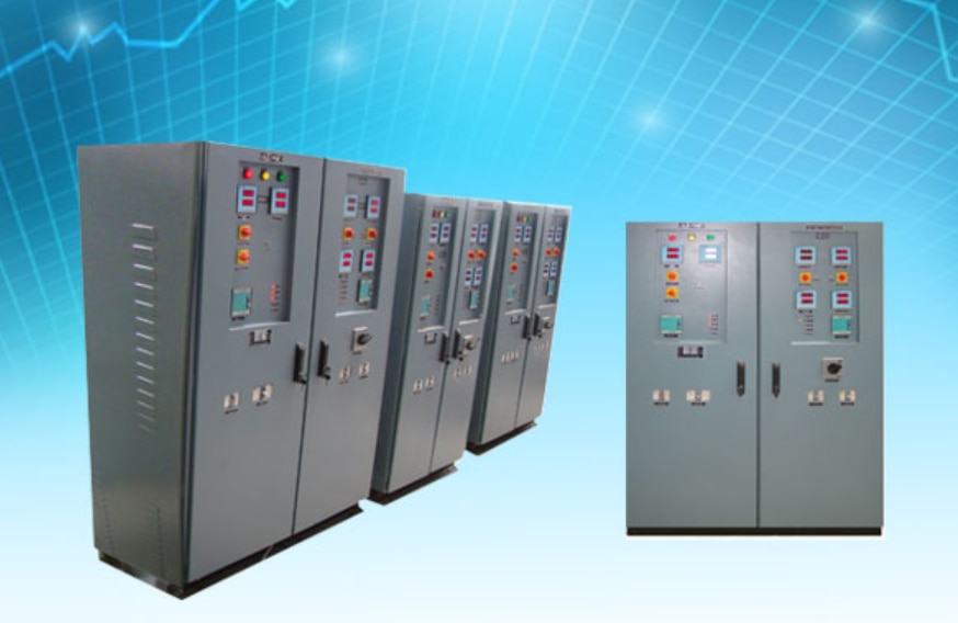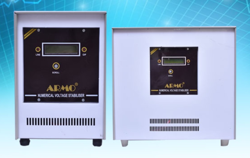
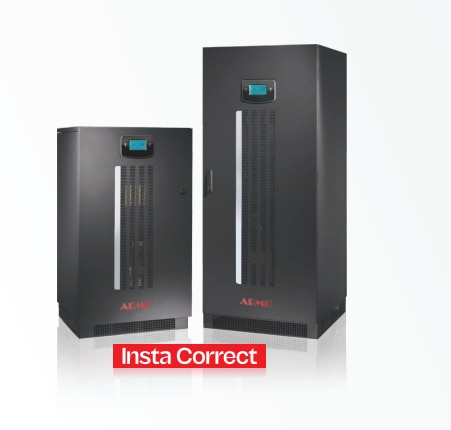
Static Stabilizer
Static Stabilizer

Silent Features Low burden Wide operating voltage range Wide frequency setting range 39.00 to 70.00 Hz Independently adjustable tripping stages two of which have a rate of change of frequency function. Consistent accuracy = +-0.03 Hz at 50 Hz Unaffected by voltage fluctuations Insensitive to harmonics & Transient Built in self-test mode Built in timer .02 to .18 sec ARMO-UFTR Frequency relays are used-to monitor the frequency of an electrical System. Due to inadvertent splitting of inner connection in power system. Isolated areas of the system may become deficient in the generation and frequency of the same may drop considerably giving rise to emergency conditions. In order to maintain control of system under this low frequency emergency,some form of graded load shedding is needed. ARMO-UFTR relay is used to detect such conditions and initiate load shedding to prevent complete system collapse. Type UFTR-41 consists of two/three definite time fully independent frequency measuring stage and one df/dt stage. Type UFTR-51 consists of two/three definite time fully independent frequency measuring stage and one df/dt stage. Separate Auxiliary relays are provided which get energized after the respective time delays (In case of df/dt the tripping frequency gradient). Tripping indications and reset push button are provided on the front of the relay. The relays are suitable for any application in industrial plants and to generators where definite time under over frequency protection with df/dt stage is required. Internal timers are provided for each operating circuits and separate aux relays ensure maximum flexibility of application. Two terminals are provided for the voltage input to the frequency sensing circuit. The measurement of the frequency is digital for which only the zero-crossing of the system voltage and not its amplitude, are of consequence. The relay is independent of the voltage fluctuations with a wide range. However the system voltage sink below a predetermined value in which the accurate measurement can no longer be expected the under voltage blocking circuit blocks all the outputs Technical Data AC voltage rating 110, 220VAC Auxiliary supplyvoltage From PT 66 to 135 V External 35 to 135 of PT Frequency setting range 39.0 to 60.0 Hz in step of 1 Hz Under frequency setting (dfdt) 1 Hz Sec to 9.9 H:: Sec at 50 Hz Operating voltage range 66 to 135 35-to 135 V The relay is blocked below & above this limit No. of tripped stageUFTR -51 UFTR-41 UFTR-6 I 4. Two of which have dfdt output One of which have dfdt output 4 No. of dfdt output Reference frequency 5 MHz Accuracy .03 Hz at 50 Hz Reset ratio 100% (Digital) Max reset time under &Overfrequency 50 ms Tripping delay for dfdt stage 5 cs to 9 cs unless stated set to 6 cs on delivery Evaluation period for delivery dfdt stages 26 52 mSunless stated set to 26 mS On Burden Aux Supply from PT 1.5VA Aux supply from an external source Aux DC /without tripping relays 1.5VA max at 150V 50Hz Contacts in relay 11 W for 4 stages Indicating signals 1 Pair of N/O reed contact 50VA max 2.5 Ad. C. Test voltage Low voltage inhibit LED LED tripping LED push button reset Reduced values are valid in case of repeat testing 2KV 50 Hz 1 min 5KV 1.2/50 usec Casting Does not apply to the terminal connected to a common Aux supply Guaranteed operation Ambient Flush mounting withrear connection 110 mmx 205mmx 250mm W H D temperature -5 – 55`C Silent Features Low burden Wide operating voltage range Wide frequency setting range 39.00 to 70.00 Hz Independently adjustable tripping stages two of which have a rate of change of frequency function. Consistent accuracy = +-0.03 Hz at 50 Hz Unaffected by voltage fluctuations Insensitive to harmonics & Transient Built in self-test mode Built in timer .02 to .18 sec.